Games like Battlefield 2 and Far Cry are very demanding for the graphics subsystem.
Unfortunately videocards are like the rest of the PC, the better the performance the
higher the pricetag. So being the cheap bastard that I am I did this thing to my X800XL
that would enable it to run way way faster -> increase the voltage.
I
started out with a simple Club3D X800XL with 256MB of 2,0ns ram.
Standard the
core would show artifacts when pushed to 450MHz, so I kept it at 440MHz.
Obviously I wanter MORE POWAH!
The memory was of surprising quality and was running happily
without any mods or cooling at 580MHz.
This means that it might not have hit the ceiling yet 
To keep the rest of the Bla-bla to a minimum I'll get to the point, so here's the list-'o-facts:
Before the mod:
Vdd =
1.81 v
Vddq = 1.88 v
Vgpu = 1.41 v
RVdd = 1140 ohms
RVddq =
850 ohms
RVgpu = 436 ohms
RIgpu = 39.2 Kohms
After the mod:
Vdd = 1.952 v
Vddq = 1.999 v
Vgpu = 1.671 v
Below I will
list only the value of the resistors that I added, you can calculate
yourself what
the actual resistance and Delta resistance on that spot
is with 1 / R = 1 / R1 + 1 / R2.
(for example 1 / R = 1 / 1140 + 1 / 10500, with this you can calculate R).
RVdd = 10.5 Kohms
RVddq = 14.45 Kohms
RVgpu = 2.29
Kohms
RIgpu = 250 Kohms
The Igpu resistor I left at 250 K
because the GPU didn't crap out at 1.671 v.
Even adding the 250 K will
lower the overal resistance so it nudged a little in the right direction
anyway.
The pics!
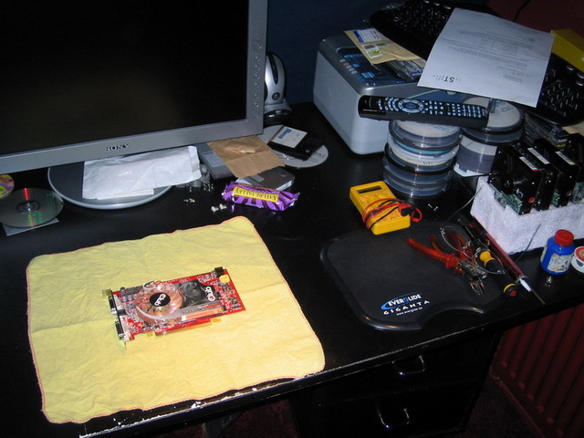
Here it all begins, multimeter, tools,
glasses and spare hard drives... just in case 
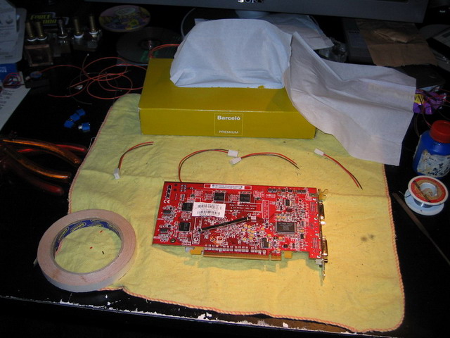
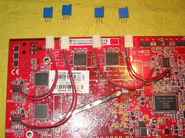
Here you see the prepared connectors for the resistors. I wanted it this way so that the resistors
may be removed and installed when needed or when there are some unexpected problems.
(I hate permanent solder
mods anyway).
In the top left corner you can see the WC blocks, ready for
mounting when my Venice came in 
Those tiny little islands are too friggin... tiny!!! 
But after several attempts it seemed to work...
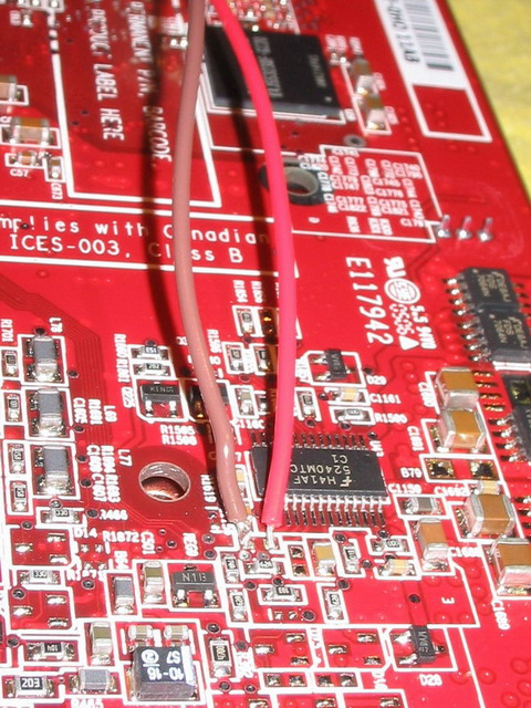
Soldering to the chips was a lot easier, I just hope no
crap flowed under the chip or else I'll be
going out to buy me another videocard... AGAIN!
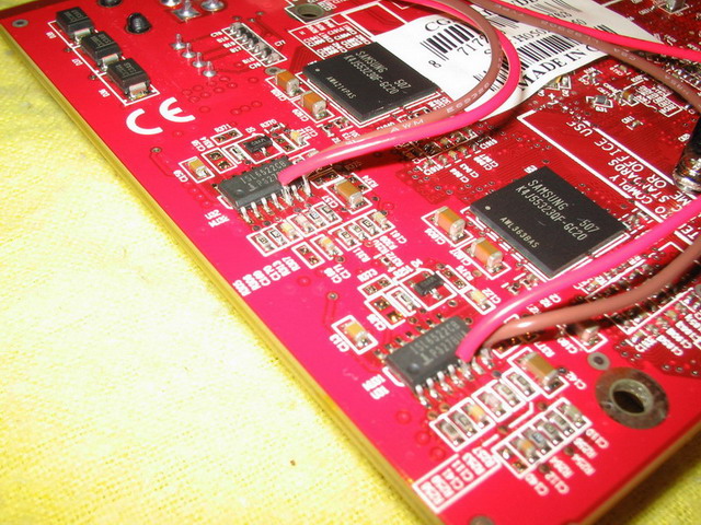
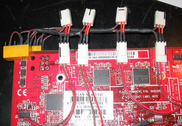
This is a nice view of how the connectors are mounted and how the
resistors will be inserted into them.
You may wonder how I will keep
them apart...
Well, like this! Some simple stripes to identify what goes
where... simple as can be!
The resistors fitted to the connectors like a glove, just perfect.
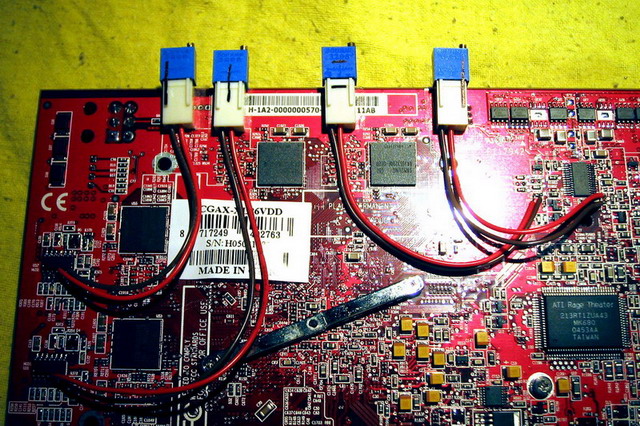
And this was the final setup... well, the initial final setup that is
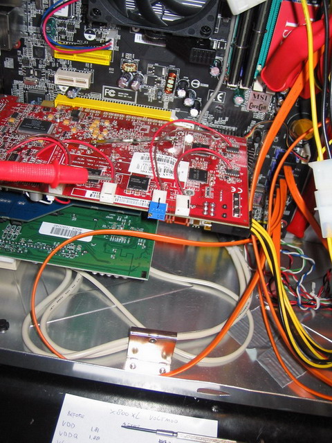
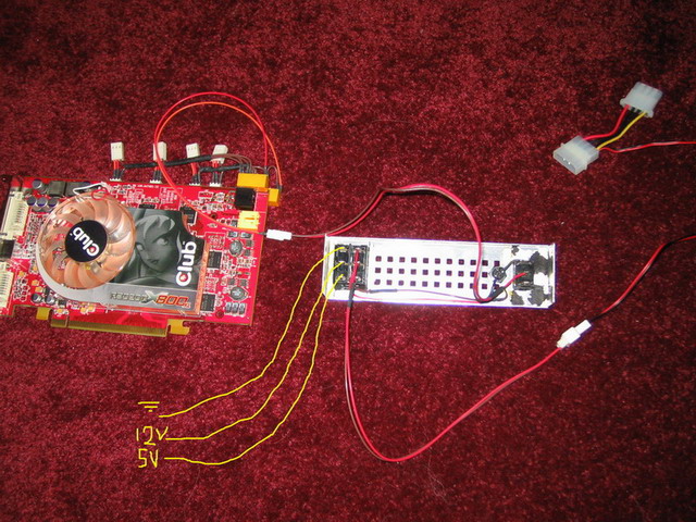
The resulting resistance testing was very important, one miss calculation and the whole thing might
go up in smoke.
Testing per resistor was
easy, just put in a little blue block, turn on pc and measure.
While the
pc was on I adjusted the screw and saw the voltages change to what I
wanted.
I'm sure the voltages could go higher with some
fiddling and trying, but right now I'll leave it at a
what seemes a
safe setting (at
least I think it's safe  ).
).
Until the watercooling and ramsinks would be installed I removed the
resistors not to stress it too much,
obviously I didn't want to leave it
running with the mod 24/7 sans cooling
This however spiked me to think about a modification to this modification...
I wanted to make the voltmod switchable so that the videocard wouldn't have to endure the
maximum voltage 100% of the time while it's needed maybe 5% of the time.
I had made an LCD display switchable with a signal from the
printerport, but that might not be stable
or reliable
enough to use it here, but a
normal switch should do the trick.
The original modded-mod design called for a 4 rail switch to switch all 4 resistors simultaneously.
But I also wanted to make the mod switch off, regardless of the mod-switch position, if I would set the fans to low (7v).
It may be a unnecessary safety feature, but it's a cool project to realise!
The whole mechanical switching of all resistors was a little too lo-tech for my taste so
I took away the
complicated 4 rail switch and I added a relais to the design, in series with a more simple 'master' switch,
the fan switch and a little blue led to tell if it's working or not (and because blue leds are kewl )
The mod modification was designed to be added on top of the existing mod.
I refused to tamper with the installed mod to avoid breaking the difficult solder connections and in
case my mod-switching-setup didn't function as intended, I wanted to be able to just take it out
and toss it into the corner without having to fix the old mod first.
As you can see in the first picture, I used two smaller relais instead of a single big one because I didn't
want
to stretch 8 wires all across the case and a bigger single relais wouldn't find enough grip on the video card.
I mounted them on the edges to avoid any interference from the field the coils generate so close the
other videocard's components (it may be small, but can still interefere).
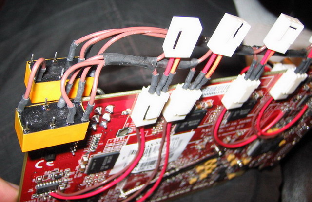
You may notice that it's now fully shrink tubed 
Here you see the complete circuit.
The yellow lines indicate the fan switch wires that I didn't solder back yet (I lengthened them while I was working on it anyway).
The other side of the fan switch switches 12v to the led and on to the second switch, the mod switch.
From there it goes to the relais and back to close the circuit.
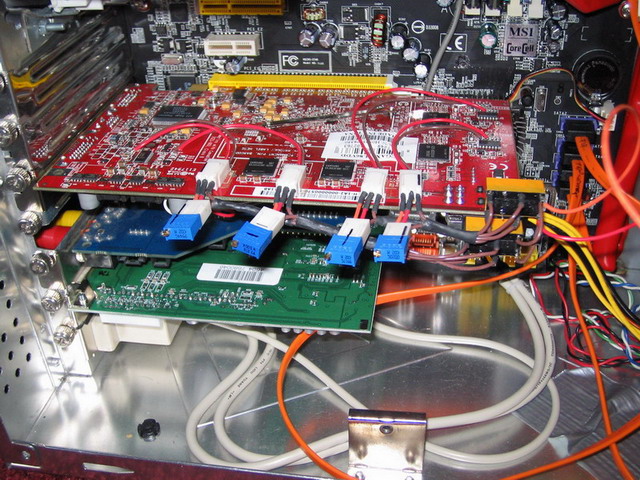
This is what the installed modded-mod looks like.
You may see a few changes on the final model compared to the previous pictures.
The two relais are now parallel as opposed to series because the voltage drop in series was too much to make them switch AND have a bright blue led in series as well.
Also the idiot at the hardware store was wrong about which pin was the common on the relais, so I had to resolder some of them.
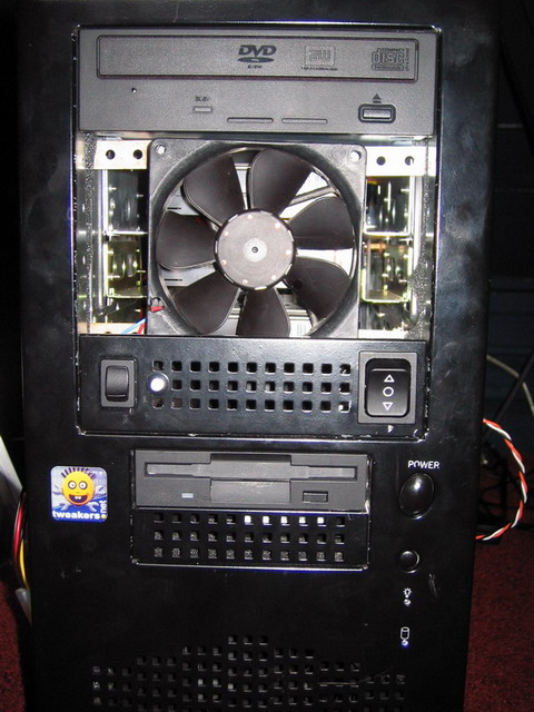
The front view with the fan switch on theright and the mod switch on the left.
The mod is now switched off.
That's about it for now.
No benches yet, my Venice should come in very soon now and once that baby is installed I'll hook up the water cooling and a benchin' we will go! 